Saturday, August 25, 2007

How to build the Fujimoto Origami Cube

Cut and Fold 
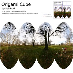
If you've been following my stream on flickr you will have seen a pattern to be folded into a cube, with a panorama printed on it so you get a "Virtual Reality Cube". The pattern looks like this (click on it to go the flickr page where you can download a large version of it). Here are the instructions to fold this cube created by Shuzo Fujimoto. You will need to refer to the pattern of folds to help you know what you need to fold. In fact, this pattern (on the upper right part of the picture) could be sufficient to let you know how to fold it, but one of the steps is tricky. You can find hand-drawn instructions.


Print and cut the square.
Fold in half, and keep folded.
Fold again in half.
Unfold the top part.
Fold down the middle.
Fold then one of the halves...
... and the other.
Unfold everything. We have all the straight line creases marked.
Fold the slanted lines, as in the pattern. Not pictured here: you have to do that 8 times in all.All the creases have been made now. It should look like this.
Now turn it around.
This is the hardest part. With your thumb and fingers, press the bottom third square from the left upwards and to the left.If all the pre-creases are correct, it should fold itself quite easily. If not, straighten them again and push...
... and push, putting the four folds in the correct position.
Fold the fourth corner below the first one to get the top of the cube to lock.Turn over and start folding the four flaps, one after the other.
When you come to the last one, fold it below the first one, and......voilą !

Labels:

Friday, August 17, 2007

I wish I had thought of that with my kids

Another way of doing a Droste with your children!

Monday, August 13, 2007

Conformal Cube: The Story of a Search

What you see here is the result of a long and complicated search, but with an enormous amount of help from Daniel M. German I've able to construct the conformal projection of the cube. If your first reaction is to mutter: "The what of the cube?" or just "So?", and if you are interested, please follow these explanations...

You may have seen before panoramas projected in a cube: in flickr for example, there is a "foldables" group and I have some myself (including other polyhedra). These panoramas have all in common the use of the gnomonic or perspective projection: in this type of projection straight lines stay straight. This is great for architectural photos, but as you can see for the model on the right, you get broken lines in the sides of the cube (the columns of the cathedral seem to be broken).

It is possible in theory to devise a conformal projection that would show the sphere as a cube. However it is very difficult to find information on such a projection. The usual internet cartography sources, if they mention this projection, give no clue at all how it can be constructed. The only reference is in this PDF file where a planisphere projected conformally in the cube is given, only quoting John Parr Snyder's personal software. John Parr Snyder is the most precious reference for mathematical cartography available on the web, and though he died in 1997 his personal BASIC program used to generate maps is the only trace left of how he constructed the conformal cube... mostly undocumented, and of course not portable at all. Furthermore, the formulas used in that program are all forward transformations, whereas the projection of an image needs the inverse formulas.

But a reference was there! a 1976 paper in Cartographica titled "Conformal Projections based on Elliptic Functions" by L.P. Lee (another incredibly talented cartographer, "who retired in 1974 as Chief Computer in the New Zealand Department of Lands and Survey") seemed to be the source for these polyhedral globes. Daniel German was very very helpful in locating this rather obscure publication (and others), and I have to thank him for that!

The conformal projection uses an incredible 1872 theorem by Hermann Schwarz who showed that "the spherical triangles into which the surface of the sphere is divided by the planes of symmetry of the regular polyhedra can be conformally represented on the infinite half-plane by algebraic transformations of the stereographic projection on the central plane so that the vertices are represented by the points 0, 1, infinity on the real axis". Unfortunately the paper is in german and is probably even harder to get, so I will able to look how Schwarz showed this...

(the source image for this shot is from the Notre-Dame-de-Reims Cathedral in Reims, France)

Saturday, August 11, 2007

Edit the Nadir and Zenith of an Equirectangular Panorama

Often the most difficult part of an equirectangular panorama (360° wide, 180° vertically) is the nadir, i.e. the bottom. This is where the tripod is, so no clear shot can be had without some sort of acrobatics to tilt the tripod away. So an important part of creating a nice equirectangular panorama is editing the nadir (and sometimes, the zenith).
The procedure I had been using so far is:
  1. Create the equirectangular image (in Gimp)
  2. Use hugin to create the rectilinear projection of the nadir, with a 90° field-of-view
  3. Edit this rectilinear image (in Gimp)
  4. Use hugin to output this edited rectilinear image into an equirectangular panorama
  5. Manually blend the extra nadir unto the equirectangular image (in Gimp).
As you can see, this needs going back and forth between Gimp and hugin, and is not very practical. Spurred by the Photoshop tool mentioned here I bring to you a Gimp/Mathmap script to create the zenith and nadir of an equirectangular panorama, edit in place and transform back.

You should first make a copy of the layer with the equirectangular image, since the transformation to and back from the zenith/nadir does not keep the part around the horizon.

Filter used to create the Zenith and Nadir:

filter ToNadirZenith (image in)
# Filter created by Seb Przd
# Licensed under the GPL

if x<0 then
sinphi1=1;
xx=x+X/2;
else
sinphi1=-1;
xx=x-X/2;
end;

yy=y;

rr=sqrt(xx^2+yy^2);

c=atan(rr/Y);

phi =
if rr == 0 then
0
else
asin(cos(c)*sinphi1)
end;

xxx=atan(xx,-yy*sinphi1)*X/pi;
yyy=phi*Y/(pi/2);

in(xy:[xxx,yyy])
end


Filter used to transform back the Zenith and Nadir:

filter FromNadirZenith (image in)
# Filter created by Seb Przd
# Licensed under the GPL

output=1;
if y>Y/4 then
sinphi1=1;
xc=-X/2;
else if y<-Y/4 then
sinphi1=-1;
xc=X/2;
else
output=0;
end;
end;

cosc=sinphi1*sin(y/Y*pi/2);
xx=cos(y/Y*pi/2)*sin(x/X*pi)/cosc;
yy=-sinphi1*cos(y/Y*pi/2)*cos(x/X*pi)/cosc;

if abs(xx)>1 then output=0; end;

if output then
in(xy:[xx*X/2+xc,yy*Y])
else
rgbaColor(0,0,0,0)
end

end